
PC817X Pinout,Schematic, Equivalent,Integrated Circuit: Features, Specification
PC817X Description
Description PC817X Series contains an IRED optically coupled to a phototransistor. It is packaged in a 4pin DIP, available in wide-lead spacing option and SMT gullwing lead-form option. Input-output isolation voltage(rms) is 5.0kV. Collector-emitter voltage is 80V(*) and CTR is 50% to 600% at input current of 5mA.
PC817X Models

3D Models
PC817X Features
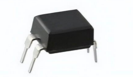
■4pin DIP package
■Double transfer mold package (Ideal for Flow Soldering)
■High collector-emitter voltage (VCEO:80V(*))
■Current transfer ratio (CTR : MIN. 50% at IF=5 mA, VCE=5V)
■Several CTR ranks available 6. High isolation voltage between input and output
Specifications
Sharp Microelectronics PC817X technical specifications, attributes, parameters
| Product Pictures | |
| Part number | PC817X |
| Mount | Through Hole |
| Mounting Type | Through Hole |
| Package / Case | 4-DIP (0.300, 7.62mm) |
| Number of Pins | 4 |
| Operating Temperature | -30°C~100°C |
| Packaging | Tube |
| Published | 2003 |
| JESD-609 Code | e0 |
| Part Status | Obsolete |
| Moisture Sensitivity Level (MSL) | 1 (Unlimited) |
| Terminal Finish | Tin/Lead (Sn/Pb) |
| Max Power Dissipation | 200mW |
| Approval Agency | UL |
| Voltage - Isolation | 5000Vrms |
| Output Voltage | 80V |
| Output Type | Transistor |
| Number of Elements | 1 |
| Configuration | SINGLE |
| Power Dissipation | 200mW |
| Voltage - Forward (Vf) (Typ) | 1.2V |
| Input Type | DC |
| Forward Current | 50mA |
| Output Current per Channel | 50mA |
| Rise Time | 18μs |
| Fall Time (Typ) | 18 μs |
| Collector Emitter Voltage (VCEO) | 80V |
| Max Collector Current | 50mA |
| Collector Emitter Breakdown Voltage | 35V |
| Rise / Fall Time (Typ) | 4μs 3μs |
| Reverse Breakdown Voltage | 6V |
| Max Input Current | 50mA |
| Collector Emitter Saturation Voltage | 200mV |
| Max Breakdown Voltage | 35V |
| Current Transfer Ratio (Min) | 50% @ 5mA |
| Current Transfer Ratio (Max) | 600% @ 5mA |
| Radiation Hardening | No |
| REACH SVHC | Yes |
| RoHS Status | Non-RoHS Compliant |
| Lead Free | Contains Lead |
PC817X Advantage
PC817X is also known as an optocoupler/optoisolator. It consists of Infrared Emitting Diode (IRED). This IRED is coupled to a phototransistor optically and not electrically. It is closed in a four (4) pin package. This package is usually available in two different forms. The first one is the wide lead (Pb) spacing option and the second one is SMT gullwing lead form option.
PC817X has an internal LED and a phototransistor. The photo transistor's base becomes activated when LED throws light on it. The output obtained can be divided into two formats either the common emitter or the common collector. But the configuration is the most common emitter. If the LED does not glow, the transistor remains off and hence there will b no output generated by the optocoupler i.e. PC817X.
PC817X has different features, e.g. double transfer mold package, current transfer ratio, different CTR ranks available, RoHS compliant, lead (Pb) free, etc. Its real-life application includes noise suppression in switching circuits, programmable controllers, signal transmission between circuits having different voltages, signal transmission between different impedance, etc.
PC817X Applications
■I/O isolation for MCUs (Micro Controller Units)
■Noise suppression in switching circuits
■Signal transmission between circuits of different potentials and impedances
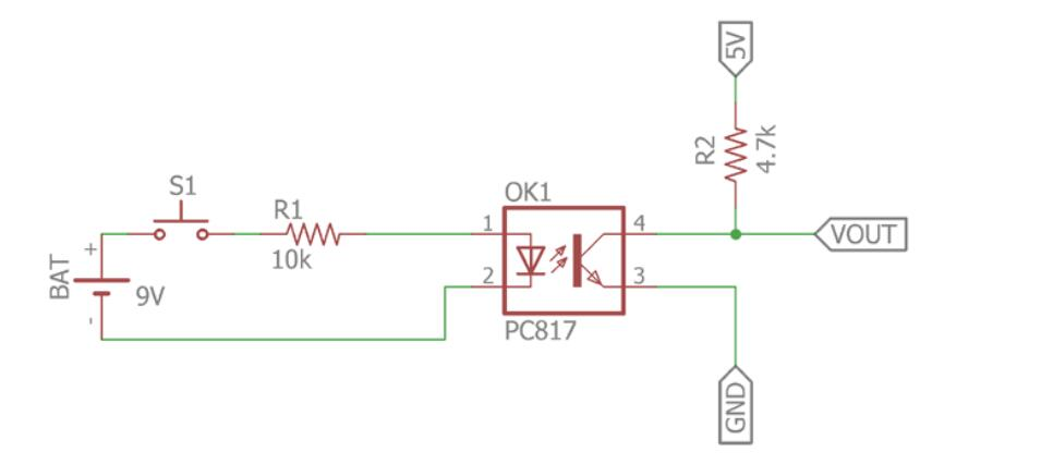
The upper circuit employs a phototransistor-based optocoupler circuit. It will operate in the same way as a standard DC transistor switch. In the schematic, a low-cost phototransistor-based optocoupler PC817 is used. The infrared led will be controlled by the S1 switch. When the switch is activated, the 9V battery source supplies current to the LED via the 10k current limiting resistor. The intensity is controlled by the R1 resistor. When we change the value and decrease the resistance, the intensity of the lead increases, resulting in a high transistor gain.
The transistor, on the other hand, is a phototransistor that is controlled by the internal infrared led; when the led emits infrared light, the phototransistor contacts and the VOUT becomes zero, effectively turning off the load connected across it. It is important to remember that the datasheet states that the transistor's collector current is 50mA. R2 provides power to VOUT 5v. The R2 resistor functions as a pull-up resistor.
Where to Use PC817X IC
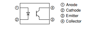
PC817X Photocoupler has a transistor that is controlled based on light (photon). So this IC basically has an IR (infrared) LED and a photo-transistor inside it. When the IR LED has powered the light from it falls on the transistor and conducts. The arrangement and pinouts of the IR LED and the photo-transistor is shown below.
This IC is used to provide electrical isolation between two circuits, one part of the circuit is connected to the IR LED and the other to Photo-transistor. The digital signal given to the IR LED will be reflected on the transistor but there will be no hard electrical connection between the two. This comes in very handy when you are trying to isolate a noisy signal from your digital electronics, so if you are looking for an IC to provide optical isolation in your circuit design then this IC might be the right choice for you.
How to use PC817X IC
Using the PC817X IC is pretty much straightforward, we just have to connect the anode pin of the IR LED (pin 1) to the logic input which has to be isolated and the cathode (pin 2) of the IR led to the ground. Then Pull high the collector pin of the transistor using a resistor (here I have used 1K) and connect the collector pin to the output of your desired logic circuit. The Emitter (pin 4) is grounded.
Note: The ground line of the IR LED (pin 2) and the ground line of the transistor (pin 4) will not be connected together. This is where the isolation occurs.
.gif)
Now, when the Logic input is low the IR LED will not conduct and hence the transistor will also be in an off state. Hence the Logic output will remain high, this high voltage can be set anywhere up to 30V (Collector-Emitter Voltage) here I have used +5V. Their pull-up resistor 1K acts as a load resistor.
But when the Logic input is made high, this high voltage should be a minimum of 1.25V (Diode Forward voltage) the IR LED conducts and so the photo-transistor is also turned on. This will short the collector and emitter and hence the Logic Output voltage will become zero. This way the logic input will be reflected in the logic output and still provides isolation between the two. The complete work can also be understood from the GIF file above.
Another important parameter to consider while using an Optocoupler is the rise time (tr) and fall time (tf). The output will not get high as soon as the input logic is made low and vice versa. The below waveform shows the time taken for the output to transit from one state to another. For PC817 the rise time (TPDHL) and fall time (TPDLH) are 18us.
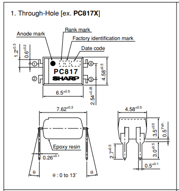
PC817X Package
PC817X Manufacturer
Sharp Corporation is a Japanese multinational corporation that designs and manufactures electronic products, headquartered in Sakai-Ku, Sakai, Osaka Prefecture. Since 2016 it has been majority owned by the Taiwan-based Foxconn Group.[3][4][5] Sharp employs more than 50,000 people worldwide. The company was founded in September 1912 in Tokyo and takes its name from one of its founder's first Ever-Sharp mechanical pencils, which was invented by Tokuji Hayakawa in 1915.


